This article, is a translation of a Dutch version, written by Joyce Beuken, published on 30 April 2021 on www.solar365.nl
To ensure that your panels do not blow off the roof during a fierce storm, PV systems (proto types) are subjected to wind tunnel tests. How do you simulate a storm?
Jeroen Weller, Research & Compliance Manager at Esdec, shares how the process works: “An angle of 10 degrees has proven to be the golden mean for our mounting system; at this angle you still catch a generous amount of sun, without the panels catching too much wind. You are looking for a balance between the maximum sun exposure, while being least bothered by the wind.”
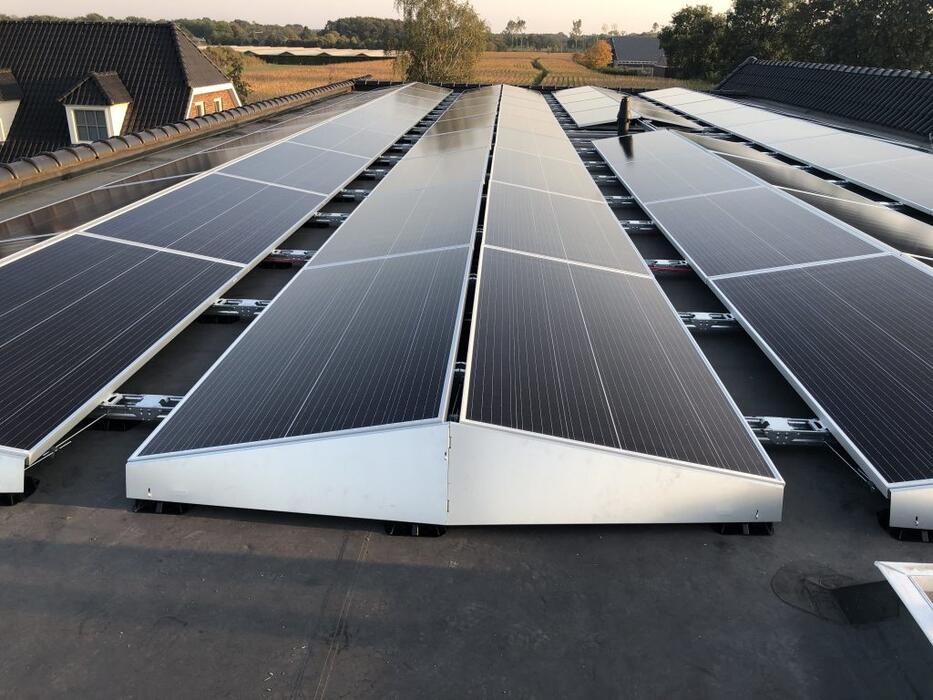
Together with the geographic location, the height and shape of a building largely determines the amount of wind load that acts on the PV systems. “How a building is designed is perhaps the most important parameter for how the wind influences the PV system.” The PV system must be designed in such a way that it adapts as well as possible to the occurring peak wind pressures, without increasing them further. “That is why we use sloping side plates in windy areas that largely close off the system, so the wind does not blow under the panels.”
There are various companies where mounting system manufacturers can collaborate with in the field of wind tunnel testing. “We chose Peutz because this is a company that thinks along with us and is also innovative at the same time,” says Weller. In a market that is still developing strongly, he believes that this provides great added value for the company.
During the wind tunnel tests at Peutz, Esdec uses scale size 1:15. The wind tunnel has been specially adapted to correctly model the boundary layer, environmental turbulence and the influence of the building on this scale.
From a historical point of view, however, most wind tunnel parties are used to using the scale 1:200 / 1:50, because this is also common in construction, Weller explains. “This has been the standard for years, until Peutz decided they wanted to use a more accurate scale especially for PV panels, specifically the 1:15 scale.” The advantage of this larger scale is that the beneficial effect of the sloping side plates, gap widths and the distance between panels can be properly taken into account. These provide pressure equalization (ed. the difference between the external and internal pressure). “We need that pressure equalization. There are no gaps because we did not want to close off the system. We need that to let the system breathe, basically.”
In the test model of FlatFix Wave, extra measuring points have been added at various places. For example, Esdec can also measure the forces that the side plates have to deal with. “From the roof support on which the system stands and the side plates, to the crevices: everything is made to scale. Esdec supplies the designs of these scale models itself”, says Weller.
“Previous FlatFix Wave concept tests showed that bolts, screws and clamps provide about 18 percent extra ‘drag’ (red. air resistance). Based on that, we decided to free the system from parts sticking out. It is built inwards for this. You only have flat parts on the outside. The panels are not screwed on but clamped.” These are things that you do not see at first glance, according to Weller, but that have been well thought out.
Weller states that in those wind tunnel tests a wide range of setups has been reviewed. “We have tested large and smaller fields, with and without side plates, but also looked at what happens if there is only something in the middle of the roof, or only a row on the side.” Are those setups that often occur? “Certainly not, but to develop a robust calculation method, you also have to measure the extremes.”
Weller concludes: “We have incorporated all data from the measurements into our ballasting method. Peutz itself has also checked this method. “
Most companies stop here. Esdec decided to give the process a tail end, with mechanical testing. “We started testing the mechanical coupling by means of so-called lift tests. This means that we lift panels to see what the other panels to which they are linked do next.”
You can read more about the mechanical tests in the third part of the triptych at the end of May.
This article is the second of three about mounting systems, wind tunnel testing and mechanical testing. The third part will be published in May.